Collaborating closely with our clients, ClearWELL provides a rapid and dedicated end-to-end service solution.
A Full-Service Solution
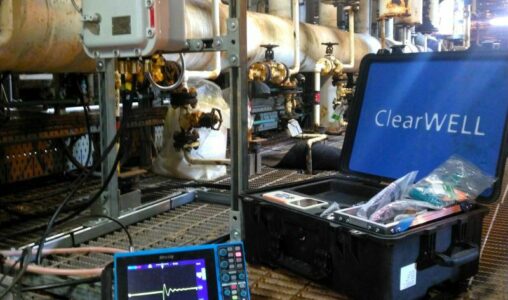
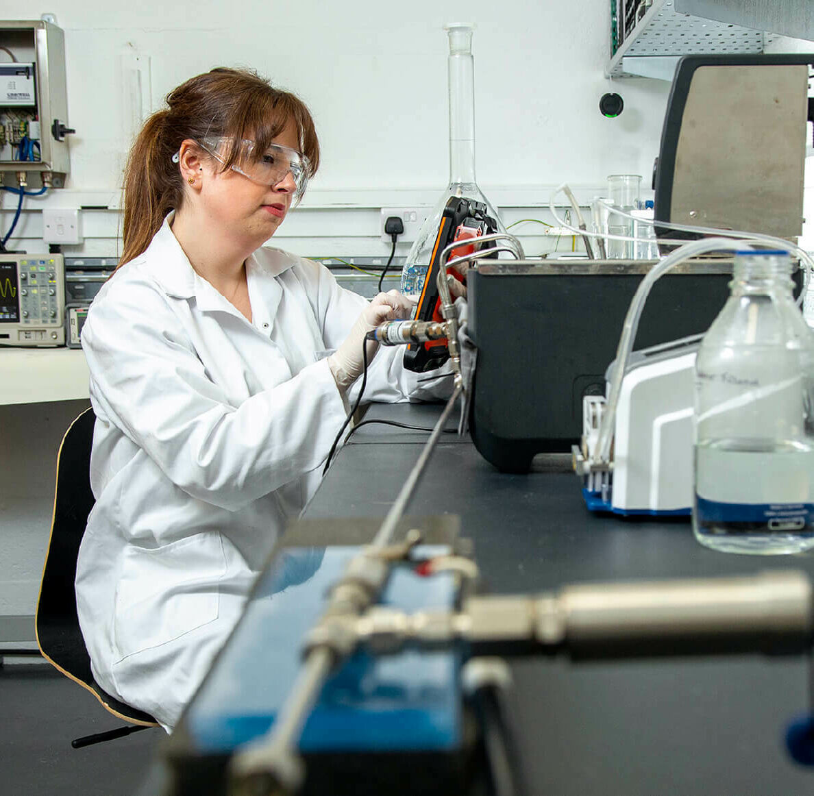
Our highly skilled and multi-disciplinary team will ensure your project is compatible with our technology prior to installation.
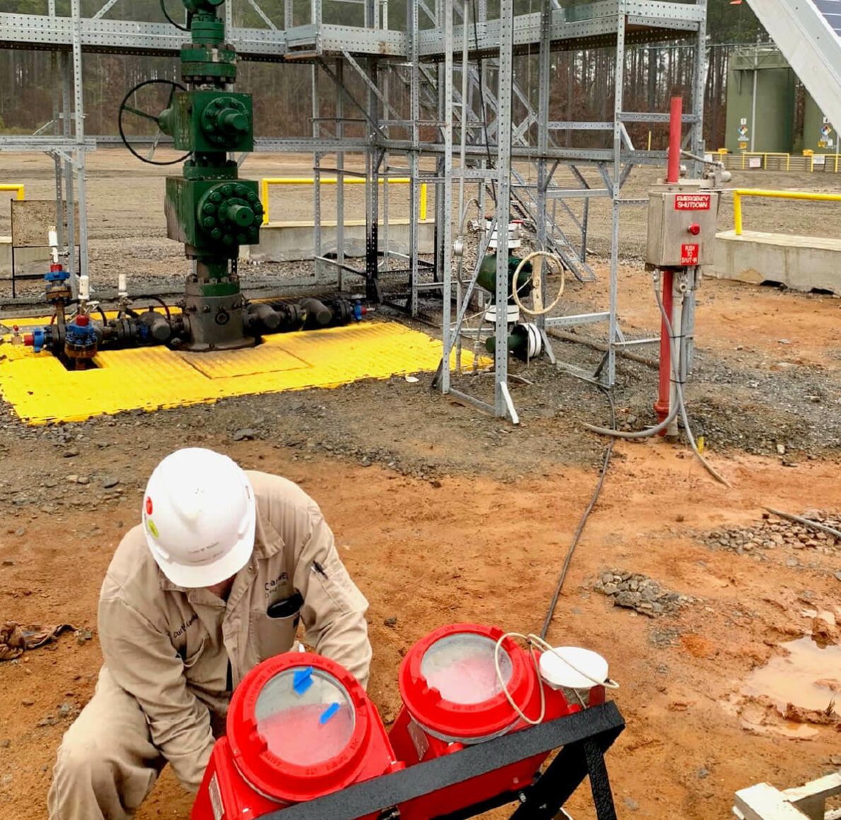
ClearWELL’s field engineers are suitably trained, qualified and compliant in all relevant safety and technical standards for site surveys, installation and maintenance work.
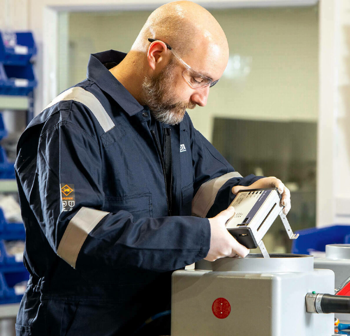
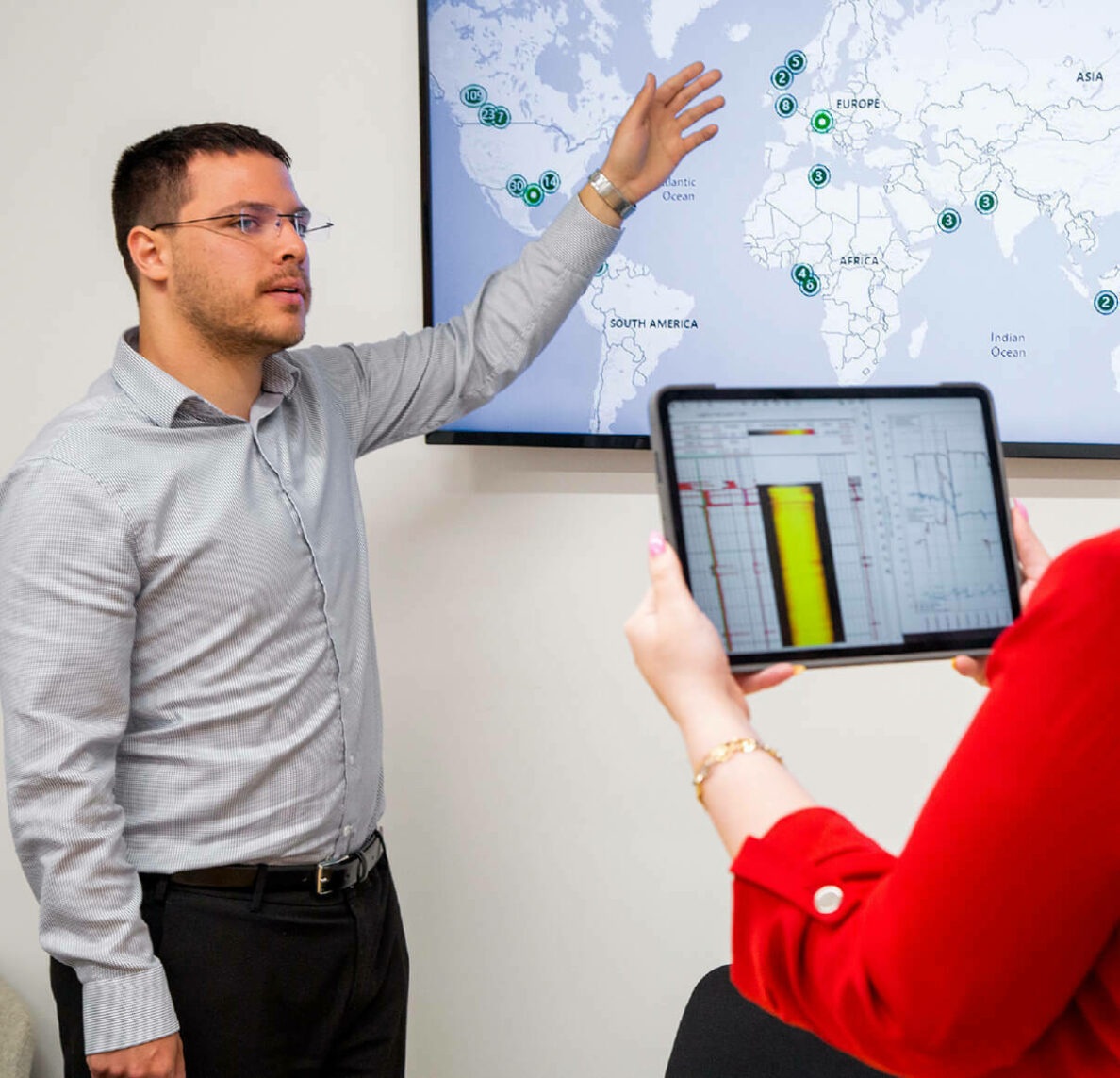
With bases in the UK, US, and Canada, plus a network of remote field engineers and approved partners, ClearWELL is able to service most global locations quickly and efficiently.
Project Assessment
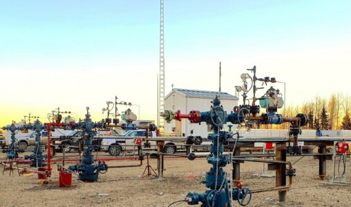
Before installing ClearWELL™, the well or facility is assessed to ensure it is a suitable candidate. This involves assessment of the well architecture, downhole devices and equipment, the well conditions such as temperature and pressure gradients, fluid chemistry, the surrounding environment and other contributing factors.
To verify our assessment of a candidate project and provide additional assurance for successful treatment, in-house scale modelling and radio frequency (RF) simulations are performed.

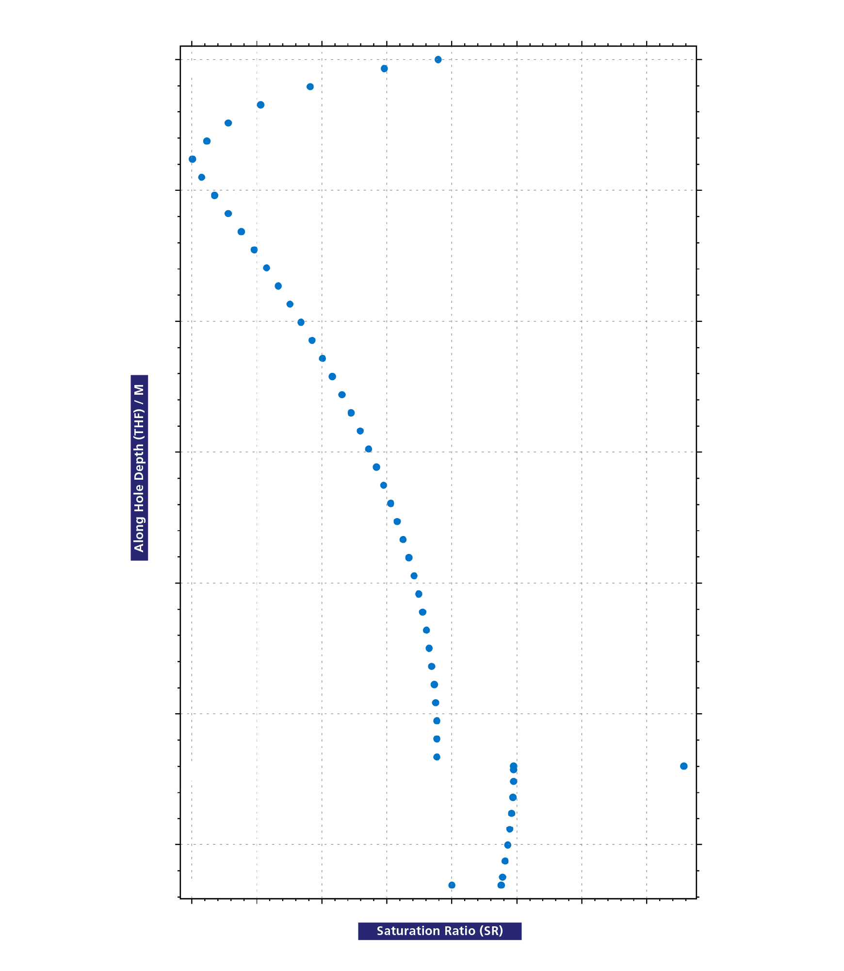
Clearlift™ saturation ratio output for calcite
Scale Modelling
Many variables can influence the amount of scale, its type and where in the process system it is likely to occur. In order to answer these questions scale prediction modelling is performed using in-house Clearlift™ software.
For a solution to precipitate scale, it must be supersaturated with a mineral (e.g. calcite or barite). The saturation ratio (SR) is used to measure the degree of supersaturation. Theoretically, precipitation will occur when the SR >1, however, typically, the SR required to result in scaling is usually higher, and many operators have their own minimum SR figures to determine the likelihood of scaling in their facilities. ClearWELL use this information alongside other variable factors to help predict the likelihood and severity of scale in each well.

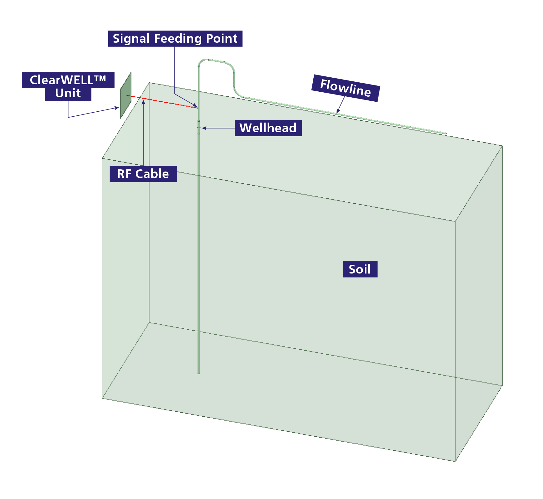
Model set up for a single pad
RF Simulation
Oil and gas wells, production facilities and geothermal systems are widely variable in their level of architectural complexity and this needs to be accounted for when installing ClearWELL™. For instance, a deep, offshore, artificially lifted well will have quite a different design to a free-flowing onshore well or a pumped geothermal system. The presence of pressure and temperature transmitters and ground paths can also have an impact on the propagation path of our RF signal along the tubulars. So, prior to installation, we use system completion schematics as part of a high-quality software simulation to analyse the electromagnetic field.
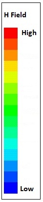
Figure 1 (a) - Front View
For these simulations we use Ansys HFSS, with finite element analysis (FEA), to give a clear picture of the likely signal path and strength. As a minimum, we consider the inner and outer production tubing diameter, the length and the material composition of the tubing and casing, plus the surrounding environment.
The following illustrations show a model set up for a single pad, onshore oil and gas well with L80 steel tubulars and casing and the associated RF simulation.
Figure 1 (a) shows the propagating magnetic field along the downhole pipe and flowline.
Figure 1 (b) - Side View
Figure 1(b) shows the surface currents along the pipe at a given point.
ClearWELL™ only requires a very small strength of signal to be effective and, as an oscillating waveform, the signal will increase and decrease at any given point over time. Therefore, a key measure is simply the existence of a signal.
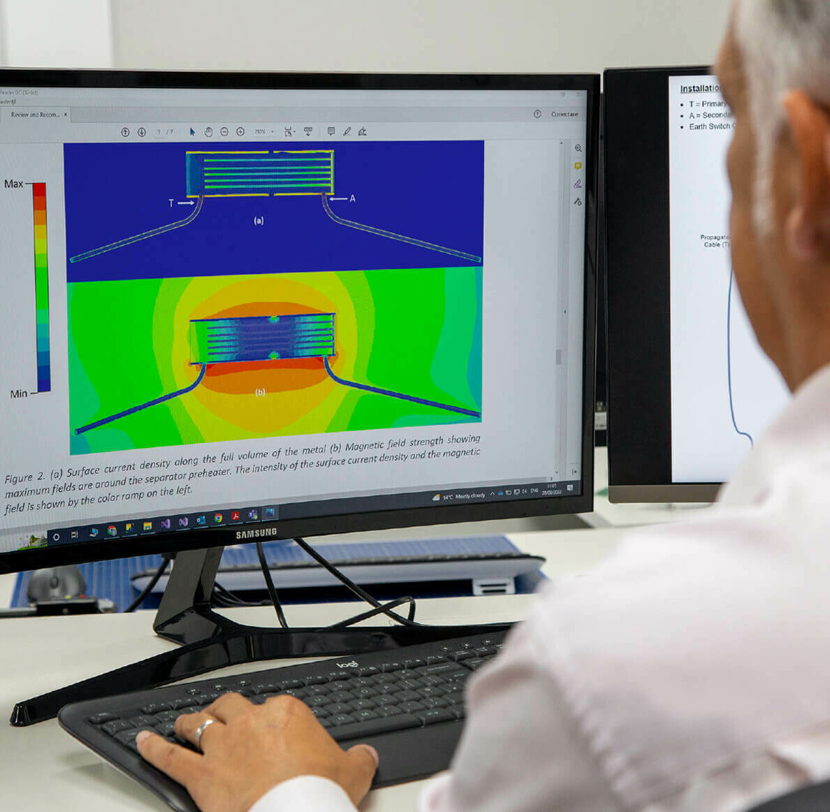
As an example of a more complex design architecture, a multi-well oil and gas pad simulation is shown below. This set-up also introduces a metal framework.
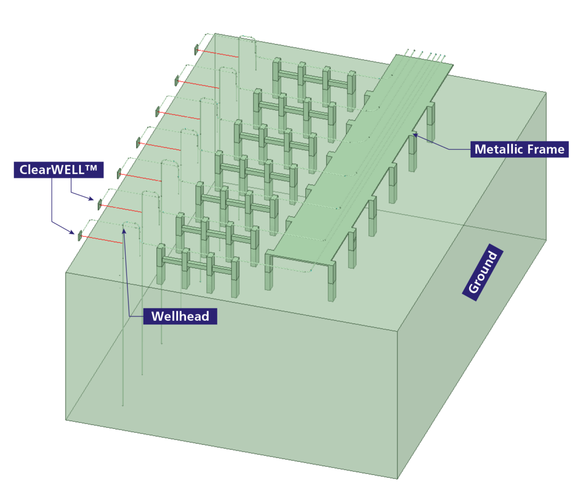

RF Simulation Showing Magnetic Field Distribution
The RF simulation opposite shows the magnetic field distribution along all seven wells. The colour ramp shows the strength of the magnetic field. This helps us to predict the strength of the magnetic field along the entire length of pipe which is then compared with our scale prediction analysis.
These are just two simple examples of ClearWELL™ simulations and do not indicate a limit in application. ClearWELL™ is operating across multiple onshore and offshore oil and gas facilities and geothermal wells around the world, protecting both downhole and surface equipment from scale.

Monitoring and After-Care
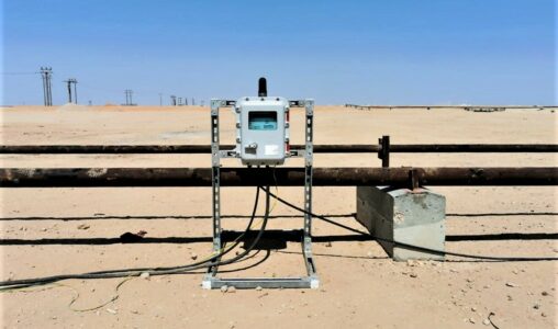
Controlling scale is an ongoing commitment over a well’s producing lifetime. ClearWELL™ technology is designed to be left in-situ to provide continuous protection and with routine monitoring it will deliver consistently high performance.
ClearWELL™ units are satellite enabled allowing them to communicate with our cloud-based remote monitoring system and log updates four times a day. The system will also generate automatic alerts in the case of, for example, a power outage or lost connection. ClearWELL engineers will analyse each unit’s performance metrics remotely and customers can also view the status of their device using our secure system.
To provide the best long-term service, with ongoing support and after-care, we ask customers to supply interim well performance metrics such as hydrocarbon and water production rates and lifting mechanism outputs, such as motor power consumption and operating temperatures. These KPIs help to provide an excellent picture of the ongoing scaling environment and efficacy of the ClearWELL™ technology over time. In turn, we use this data during routine site checks to make modifications to the set-up if necessary.
ClearWELL has completed a large number of installations at different types of facilities all over the world. To view a selection of these, or more in-depth case studies demonstrating the value delivered by our technology, please take a closer look at our News page.